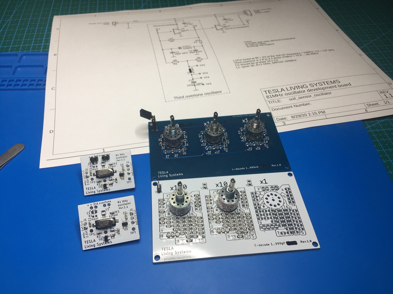
As written in the previous post, there was a need to properly tune the 3rd overtone components. While we could simply solder and desolder the two components directly on the first version of the TESLA SS01 Capacitive Soil Sensor, it quickly became tedious.
We have decided to obtain two items: an inductance decade box and a capacitance decade box. Browsing for them we have discovered they are mostly offering them with larger values, or they are very expensive. At the end we have designed our own. We have purchased very accurate SMD components and made it into a really fun project.
If you are interested in empty PCBs from our project, just email us. We can send you one set (L-decade and C-decade PCB) for 11 Eur. The price includes shipping to your door via Slovak Post Office International Economy service.
It was clear to us from the beginning, with these small values in 1pF steps and 1nH steps, our equipment (or any other actually) will have quite a large offset error stemming from the hookup wires, PCB and the rotary switches. We knew that, but we also knew it will not matter – what will remain true is that turning the switches to higher values will increase the actual values. We realize this doesn’t replace proper calculations – but it certainly fine tunes those calculations very well for a specific project in a real world scenario.
For example, if the offset error from the decade is 40 pF, each time when we add 1pF on the decade the offset will remain relatively the same and the resulting value will grow about 1pF. Our goal was to find the lowest and the highest capacitance setting on the decade box, within which the oscillator stayed reliable in the 3rd overtone frequency of 81MHz. Then we dialed the rotary switch to the middle position in-between those two, judging it to be the ideal value.
Yes, we couldn’t use the reading of the dial on the decade as an absolute value. But we could be street-smart and use it as a proper reference. Using our inexpensive LC meter, we measured the value of the C-decade in this middle position. We noted the displayed value and recorded it as a pure reference. Then we disconnected the C-decade from the meter and started to connect individual precision capacitors until we read the same value on the meter. We couldn’t take the meter value as absolute either, but we knew the attached component was matching our decade! All we had to trust is the manufacturer and their claim of +/-1% of the component value. Just to make sure we are correct, we repeated this with several components from the same wheel to verify the C-meter reference remains about the same. Then we simply accepted the capacitor value as the proper value for our circuit.
We did exactly the same with inductors. Once we went trough the whole exercise, we could correct our schematics and the BOM and the 3rd overtone component ‘calculation’ was over.
We were pleased to learn, that after this the oscillator started reliably after each power up. We reworked the LC components on all soil sensors and called it a day!

